Introduction
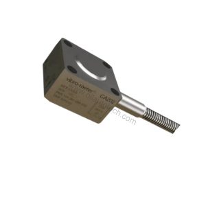
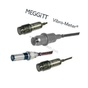
Machine monitoring has evolved from periodic manual checks to continuous, API 670-based protection chains. The Vibro Meter 111-412-000-013-A1-B1-E010-F1-G010-H10 sits at the front of that chain: a non-contact proximity measuring system built on the eddy-current principle for shaft relative vibration and gap/position measurement.
This Meggitt (Vibro-Meter) unit carries a 1.0 m integral cable, a 1.0 m flexible hose and a 10 m total system length, with an M10 × 1 body thread and standard environment rating. It weighs just 0.22 kg, so it installs quickly and puts minimal load on the machine casing.
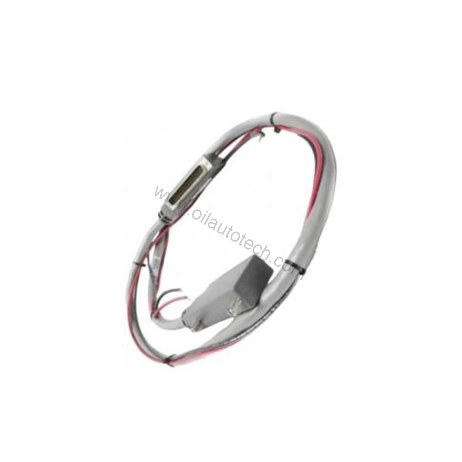
Why This Proximity System Fits Real Machines
Condition monitoring only works when the sensor survives the environment. The transducer operates from −40 to +180 °C with drift below 5%, and the transducer head is rated IP68 according to IEC 60529. It withstands 5 g peak vibration between 10 and 500 Hz and 15 g peak shock (half sine-wave, 11 ms duration) per IEC 60068-2-26 and IEC 60068-2-27.
Frequency response runs DC to 20 kHz (−3 dB), and the measurement range is 2 or 4 mm. That combination captures both slow thermal growth and fast rotor dynamics on the same channel.
Technical Specifications
| Parameter | Value |
|---|---|
| Product type | Proximity measuring system |
| Measurement principle | Eddy-current, non-contact |
| Body thread | M10 × 1 |
| Integral cable length | 1.0 m ±100 mm |
| Flexible hose length | 1.0 m |
| Total system length | 10 m |
| Measurement range | 2 or 4 mm |
| Frequency response | DC to 20 kHz (−3 dB) |
| Transducer temperature | −40 to +180 °C |
| Protection rating | IP68 (transducer head) |
| Vibration | 5 g peak, 10 to 500 Hz |
| Shock | 15 g peak, 11 ms half sine |
| Weight | 0.22 kg |
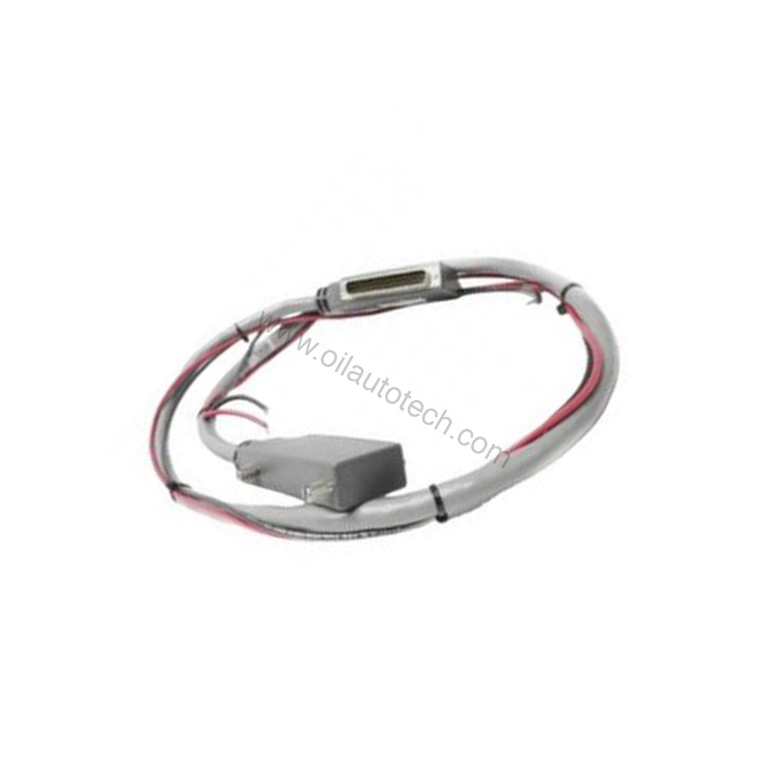
Applications Across Oil, Gas and Industry
Compressor and turbine trains rely on shaft relative vibration data to detect imbalance, misalignment and bearing wear before damage occurs. The 111-412-000-013-A1-B1-E010-F1-G010-H10 feeds that data into VM600Mk2/VM600 and VibroSmart machinery monitoring systems, which suits API 670 protection chains.
In hazardous areas, Ex certified versions of this product line support use in potentially explosive atmospheres. The temperature-compensated design keeps readings stable as process conditions shift, and voltage or current output with short-circuit protection simplifies integration into existing cabinets.
Installation and Integration Notes
Mount the transducer using the M10 × 1 thread, then hand-tighten the self-locking miniature coaxial connectors until locked. The transducer requires a high-frequency power source from an IQS900 signal conditioner, so confirm the conditioner is present before commissioning.
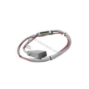
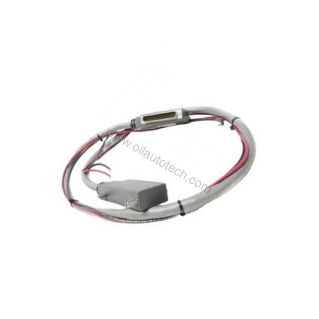
Integral and extension cables use FEP covered 70 Ω coaxial cable with a 3.6 mm diameter. The optional flexible stainless steel hose adds mechanical protection but is not leak-tight, while the FEP sheath resists most chemicals and limits moisture ingress. When wiring into fieldbus-based monitoring networks, an external gateway or connection module may be required — confirm cables and gateways with your supplier.
Maintenance and Reliability
Inspect the transducer tip, cable routing and connectors periodically, and follow the manufacturer’s safety manual for all work. Keep the probe away from impact and excessive cable flexing, since the coaxial cable is the most common wear point. Because the head is IP68 rated and the body is stainless steel AISI 316L with a Torlon tip, the unit tolerates washdown and chemical exposure in most plant environments.
Please verify current lifecycle status and availability with Oil AutoTech before ordering.
Selection Checklist
Before buying, confirm thread size, total system length, cable and hose length, measurement range, and the signal conditioner you will pair with the probe. Oil AutoTech offers hands-on technical selection help and fast dispatch, worldwide, so you get spares when you need them. Contact Oil AutoTech today for pricing and availability.