Room 7A, No. 59 Hubin North Road, Siming District, Xiamen City, China sales@oilautotech.com +86 181 5089 9927

ABB

07 KT 94 | ABB Advant Controller 24DI/16DO/8AI/4AO

  • Model 07 KT 94
  • Type Power Supplies
  • Condition In Stock
ABB
4.6/5 (16 reviews)
$259.00 Indicative price · request a quote for availability

ABB Advant Controller 07 KT 94 with 24 digital inputs, 16 transistor outputs, 8 analog inputs and 4 analog outputs. Ready-to-ship from Oil AutoTech.

Product Description

Introduction

Plant managers remember the days when a single controller could run an entire production line without a network of external modules. The ABB Advant Controller 07 KT 94 GJR5252100R0161 brings that era of practical, self-contained control into modern oil, gas and industrial automation cabinets. It is a compact DIN-rail module that combines digital, analog and counter functions in one housing, so you spend less time on panel wiring and more time on throughput.
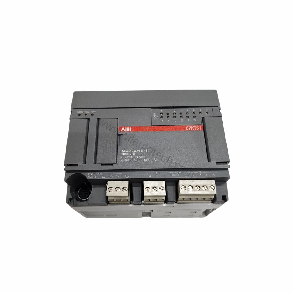
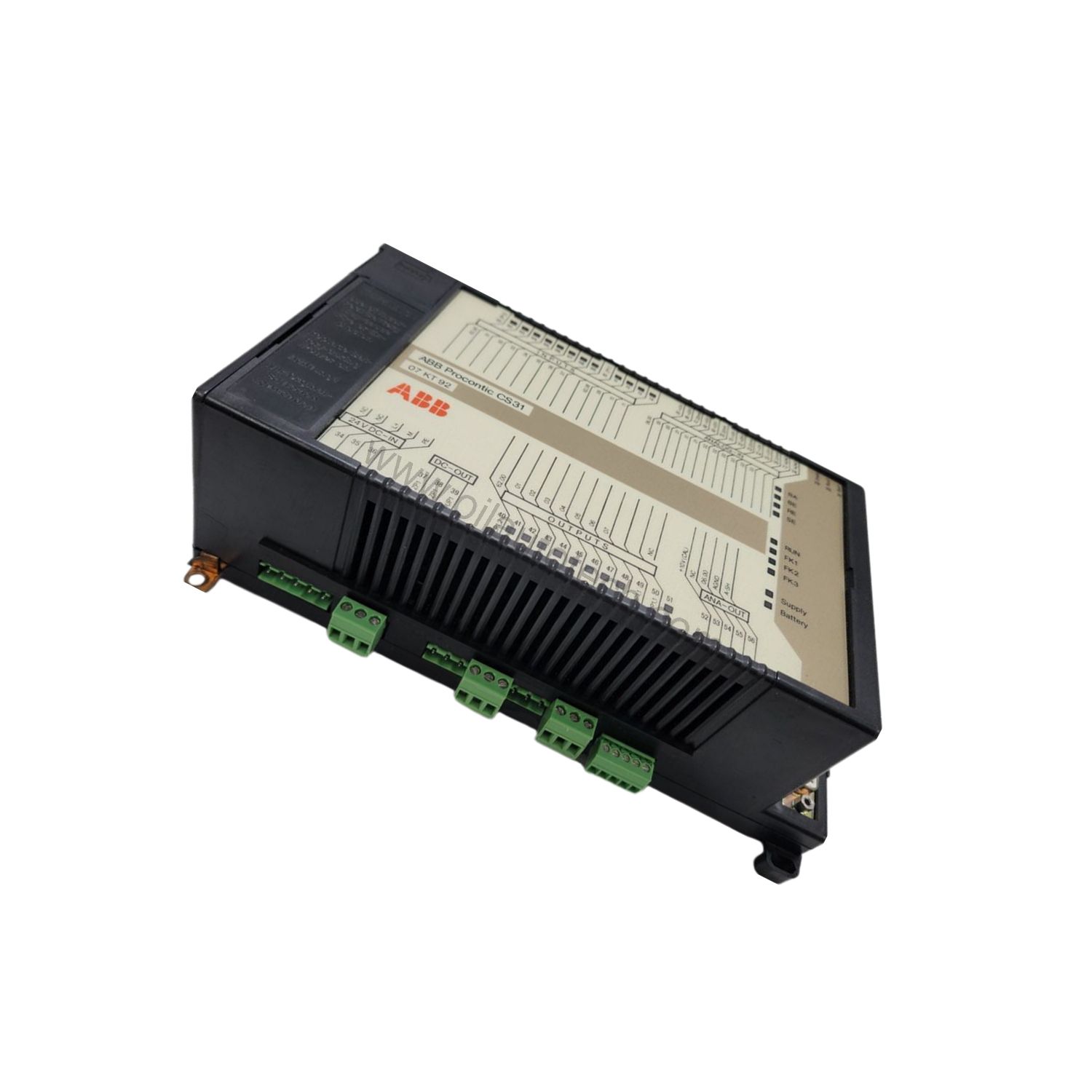
Figure 1: Front view of the ABB 07 KT 94 industrial automation component showing its physical design and enclosure.

What the 07 KT 94 Delivers

The 07 KT 94 is built around a 24 V DC supply with a maximum current consumption of 0.35 A. It provides 24 digital inputs, 16 digital transistor outputs, 8 configurable digital inputs/outputs, 8 analog inputs and 4 analog outputs. The integrated high-speed hardware counter runs in 7 operating modes with a counting range of -32768 to +32767 and a maximum counting frequency of 50 kHz. Flash EPROM memory totals 512 kB, and RAM reaches 2 MB. A real-time clock with 1-second resolution keeps event logging practical.

Technical Specifications

Parameter Value
Digital inputs 24 channels, 3 groups of 8
Digital transistor outputs 16 channels, 2 groups of 8
Digital inputs/outputs 8 channels, 1 group
Analog inputs 8 channels
Analog outputs 4 channels
Rated supply voltage 24 V DC
Current consumption max. 0.35 A
High-speed counter 7 modes, max. 50 kHz
Flash EPROM 512 kB
RAM 2 MB
Dimensions 240 x 140 x 85 mm
Weight 1.6 kg

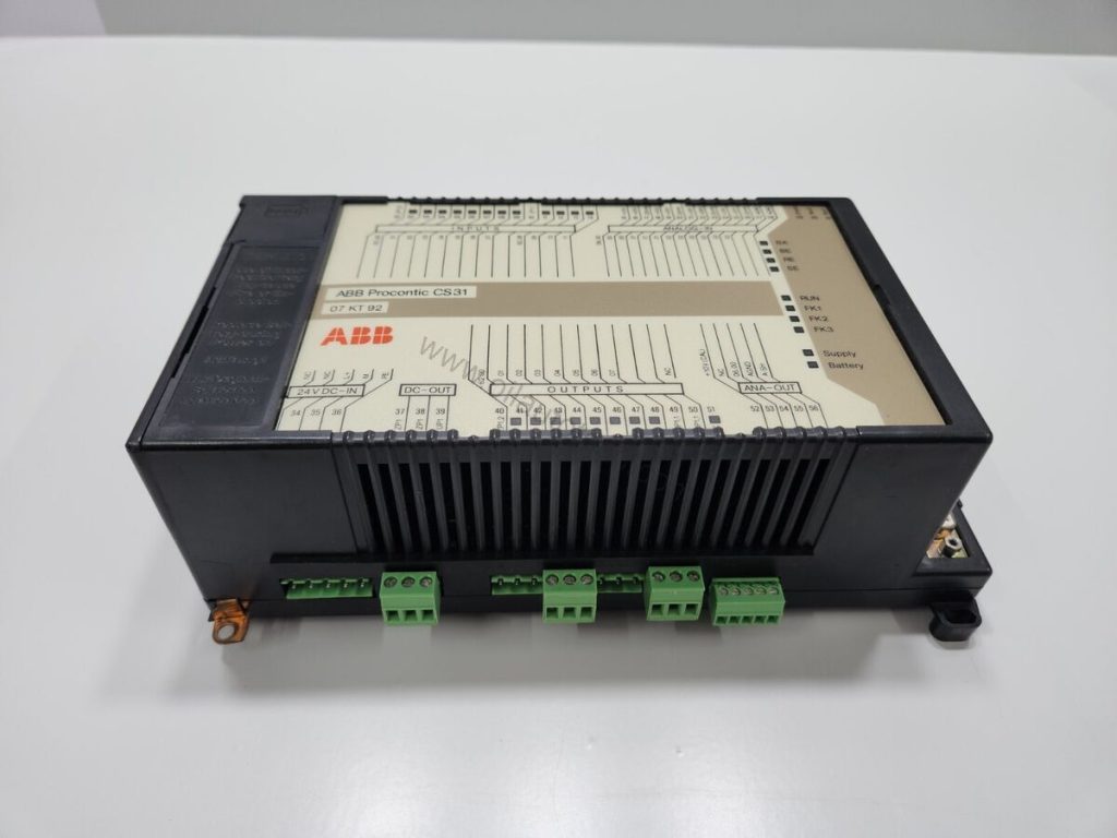
Figure 2: Technical layout and connection details for the ABB 07 KT 94 industrial automation component.

Where It Fits

The 07 KT 94 suits oil and gas skids, burner management panels and remote I/O cabinets where mixed signals arrive at one point. Its 24 digital inputs handle limit switches and pushbuttons, while the 8 analog inputs accept 0…10 V, 0…20 mA, 4…20 mA or Pt100 signals. The 4 analog outputs drive proportional valves or chart recorders. With CS31 system bus expansion, you can add up to 31 remote modules, reaching 992 digital inputs and 992 digital outputs.

Installation and Integration

Mount the 07 KT 94 on a DIN rail according to DIN EN 50022-35, 15 mm deep, or fasten it with four M4 screws. Wiring uses removable screw-type terminal blocks; power supply and CS31 bus terminals accept up to 1 x 2.5 mm2 or 2 x 1.5 mm2, while other terminals accept 1 x 1.5 mm2. Two serial interfaces support programming or man-machine communication, and one parallel interface connects a communication processor for networking with other bus systems. When integrating into fieldbus networks, confirm any required gateway or connection module with your supplier.

Reliability and Maintenance

Diagnostics cover cycle time monitoring, battery monitoring, syntax errors and checksum monitoring. Sixty LEDs show operating statuses and errors at a glance, including per-channel input and output states. The RAM contents are backed by a lithium battery module 07 LE 90 with a typical lifetime of 5 years at 25 degrees C. Inspect the battery periodically and follow the manufacturer’s safety manual for all service work. Please verify current lifecycle status and availability with Oil AutoTech before ordering.

FAQs

What is the supply voltage of the 07 KT 94?

It operates on a rated 24 V DC supply with a maximum current consumption of 0.35 A.

How many analog channels does the 07 KT 94 provide?

It offers 8 analog inputs and 4 analog outputs, configurable for voltage, current or Pt100 signals.

Can the 07 KT 94 be expanded?

Yes. CS31 system bus expansion supports up to 31 remote modules, reaching 992 digital inputs, 992 digital outputs, 224 analog input channels and 224 analog output channels.

What is the maximum counting frequency?

The integrated high-speed hardware counter reaches a maximum counting frequency of 50 kHz across 7 operating modes.

How is the 07 KT 94 mounted?

It mounts on a DIN rail according to DIN EN 50022-35, 15 mm deep, or can be fastened with four M4 screws.

Contact Oil AutoTech today for pricing and availability.
Specifications

Model / No. 07 KT 94
Product Type Power Supplies
Brand ABB
Condition In Stock
Origin Switzerland
Warranty 12 Month
Price $259.00

Additional Information

ABB Advant Controller 07 KT 94 GJR5252100R0161

Number of digital inputs 24
Number of digital transistor outputs 16
Number of digital inputs/outputs 8
Number of analog inputs 8
Number of analog outputs 4
I/O expansion via CS31 system bus by up to 992 digital inputs
992 digital outputs
224 analog input channels
224 analog output channels
max. 31 remote modules altogether
Number of serial interfaces 2 (for programming or connection to man-machine
communication)
Number of parallel interfaces 1 special interface for connection of a communication
processor (for networking with other bus systems)
Integrated memory Flash EPROM 512 kB
(240 kB program + 120 kB user data)
RAM 2 MB
(240 kB program with on-line programming)
Resolution of the integrated real-time clock 1 second
Data of the integrated high-speed hardware counter
Number of operating modes 7
Counting range -32768...+32767 (16 bits signed integer)
Counting frequency max. 50 kHz
Processing time, 65 % bits, 35 % words typ. 0.3 ms/kB program
Number of software timers any (max. 80 simultaneously active)
delay time of the timers 1 ms...24.8 days
Number of up/down counter software blocks any
Number of bit flags 8192
Number of word flags 8192
Number of double word flags 1024
Number of step chains 256
Number of constants KW 1440
Number of constants KD 384
Diagnosis Cycle time monitoring, battery monitoring, detection of
syntax errors and checksum monitoring
Indication of operating statuses and errors 60 LEDs altogether
Wiring method removable screw-type terminal blocks
Power supply, CS31 system bus max. 1 x 2.5 mm2
or max. 2 x 1.5 mm2
(see also page 4-9)
all other terminals max. 1 x 1.5 mm2
4.7.2 Power supply
Rated supply voltage 24 V DC
Current consumption max. 0.35 A
Protection against reversed polarity yes
4.7.3 Lithium battery
Battery for backup of RAM contents Battery module 07 LE 90
Lifetime at 25°C typ. 5 years
4.7.4 Digital inputs
Number of channels per module 24
Distribution of channels into groups 3 groups of 8 channels each
Common reference potential
for group 1 (8 channels) ZP0 (channels 62,00...62,07)
for group 2 (8 channels) ZP1 (channels 62,08...62,15)
for group 3 (8 channels) ZP2 (channels 63,08...63,15)
Electrical isolation between the groups,
between groups and other circuitry
(see also Fig. 4–4)
Signal coupling of input signals with optocoupler
Configuration possibilities of the inputs
Input signal delay typ. 7 ms (configurable to 1 ms)
Channels E 62,00 and 62,01 configurable for the high-speed counter
Signalling of input statuses one green LED per channel,
the LEDs correspond functionally to the input signals
Input signal voltage
Signal 0 -30 V...+ 5 V
Signal 1 +13 V...+ 30 V
Input current per channel
Input voltage = +24 V typ. 7.0 mA
Input voltage = + 5 V > 0.2 mA
Input voltage = +13 V > 2.0 mA
Input voltage = +30 V < 9.0 mA Max. cable length, unshielded 600 m Max. cable length, shielded 1000 m 4.7.5 Digital outputs Number of channels per module 16 transistor outputs Distribution of channels into groups 2 groups of 8 channels each Common supply voltage for group 1 UP3 (channels 62,00...62,07) for group 2 UP4 (channels 62,08...62,15) Electrical isolation between the groups, between groups and other circuitry (see also Fig. 4–4) Signalling of output statuses one yellow LED per channel, the LEDs correspond functionally to the output signals Output current Rated value 500 mA with UP3/4 = 24 V Maximum value 625 mA with UP3/4 = 24 V + 25% Leakage current with signal 0 100 kΩ
current input ca. 330 Ω
digital input ca. 4 kΩ

Resolution 10 to 12 bits, depending on the configuration,
see also Fig. 4-19
Resolution range ±10 V ca. 5 mV
range 0...10 V ca. 5 mV
range 0...20 mA ca. 5 µA
range 4...20 mA ca. 4 µA
Relationship between input signal and hex code -100 %...0...+100 % = 8008H...0000H...7FF8H
(-32760...0...32760 decimal)
Conversion inaccuracy caused by non-linearity,
temperature sensitivity, ageing, adjustment error on
delivery and resolution: U, I typ. 0.5 %, max. 1 %
Pt100 typ. 1 °C, max. 2 °C
Threshold,
if analog input is configured as digital input ca. 7 V
Max. cable length,
2-core shielded and cross section ≥ 0,5 mm2 100 m
4.7.8 Analog outputs
Number of channels per module 4
Reference potential AGND2 (channels 06,00...06,03)
Electrical isolation none (see also Fig. 4–4).
Max. permissible potential difference between
Terminal M (minus pole of the power supply voltage)
and terminal AGND (analog I/O minus pole) ± 1 V
Signalling of output statuses none
Output signal ranges (configurable) -10 V...0...+10 V
0...20 mA
4...20 mA

4.7.12 LED displays
LEDs for indication of:
– Statuses of digital inputs 1 green LED per channel
– Statuses of digital outputs 1 yellow LED per channel
– Statuses of digital inputs/outputs 1 yellow LED per channel
– Power supply on 1 green LED
– Battery 1 red LED
– Program is running (RUN) 1 green LED
– Error classes (FK1, FK2, FK3) 1 red LED per error class
– CS31 system bus is running (BA) 1 green LED
– bus-specific errors (BE, RE, SE) 3 red LEDs
– Overload/short-circuit of digital outputs 1 red LED
4.7.13 High-speed hardware counter (see 4.6 High-speed counter)
Data of the integrated high-speed hardware counter:
Configurable in 7 operating modes
Counting range -32768...+32767 (16 bits)
Counting frequency max. 50 kHz
Used inputs E 62,00 and E 62,01
Used outputs A 62,00

4.7.14 Mechanical data
Mounting on DIN rail according to DIN EN 50022–35, 15 mm deep.
The DIN rail is located in the middle between the upper
and the lower edge of the module.
Fastening by screws with 4 screws M4.
Width x height x depth 240 x 140 x 85 mm
Wiring method by removable terminal blocks with screw-type terminals
Power supply terminals, CS31 system bus max. 1 x 2.5 mm2
or max. 2 x 1.5 mm2
All other terminals max. 1 x 1.5 mm2
Weight 1.6 kg

Shipping & Returns

Shipping Port
Xiamen
Shipping Details
Ships within 1-3 business days after payment via DHL / FedEx / UPS Express, or by sea/air freight for bulk orders. Tracking number is provided the same day the parcel leaves our warehouse.
Return Policy
30-day return for unused items in original packaging. All parts are covered by a 12-month warranty against defects; DOA units are replaced free of charge.

Downloads

Download Instruction Manual (ABB_ABB_07_KT_94_Service_Manual)

Latest News

View All News